

 Reply With Quote
All I have is this:
Not sure where it came from
David


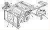
Does anyone have a diagram for the later V6 cooling set up? I'm interested in the options for the feed out of the rear cylinder head and the lower part of the thermostat housing.

All I have is this:
Not sure where it came from
David

Dave's diagram looks to be from an older V6 (just the 12 valve version?) where the cooling pipes exit through the cam belt end of the engine (what was the front of the engine when it was installed longitudinally).
Here are some pictures of my engines cooling connections:
So to set a reference point; we're looking from here:
Looking down past the bottom corner of the battery you can see the two hoses heading forward and down to the centre tunnel and off the to radiator.
Turning right from the above picture you can see (on the right) the two hoses which originally when to and from the heater matrix and the expansion tank (on a 166).
Here are the same two hoses from a different angle (the large top blue hose connects the air filter to the throttlebody, the next down is the air supply to the IACV). The fitting in the cooling hose contains a flow restriction and the thermostat for the dash temperature gauge.
Last picture from the rear of the engine bay and the above two cooling hoses can be seen connected to an expansion tank come swirl pot.
I'll try to find some diagram from the Maintenance CDROM to show this in a clearer way - more likely what you wanted
Here's one of the thermostat housing before any hoses where attached:
Probably makes the above avalanche of picture make more sense.
Last edited by Jeff; 17-04-2015 at 17:16.
Ahh .. found it (the diagram), here:

It is good practice to fit a London taxi (LT1 / TX2 - TX1) heater control valve about £19.99 in the heater circuit this allows water to flow when the heater unit is turned off, this stops the build up of gasses in the rear cylinder head and follows the original Alfa 24v system
Ken
Thanks All,
Dave's diagram is the later 164 24V set up. While Jeff's is the 156/166 set up I'm interested in... If I'm correct, the rear cylinder connection runs to the heater matrix and returns to the lower thermostat housing connection. This I assume, allows the heater to warm up without waiting for the thermostat to actuate?
As my heater is fed from the 2 main rad pipes the original heater feed can be looped /linked together with a T to the expansion tank?
Thanks Ken, I've got a taxi control but have yet to fit as I don't have the additional small diameter heater pipe installed. Is the additional pipe / control worth fitting?
Yes Ken, there was some discussion batting backwards and forwards about "what to do" with these connections when I was wondering what to do. In the end I cheated a little in that the point where the temperature sensor is installed reduces the bore diameter down to about 10mm. This allows water to flow through the circuit clearing air out of the coolant and the cylinder head in question but without directing too much water away from the primary cooling circuit. It also provided the perfect location to put the header tank at the highest point (but at the cost of moving the battery to the front of of the engine bay).
Well, that's my thought on how it ought to work. Seems to be OK so far.
Last edited by Jeff; 17-04-2015 at 17:18.
 Posting Permissions
Bookmarks